What Defines Precision in Automotive Plastic Parts
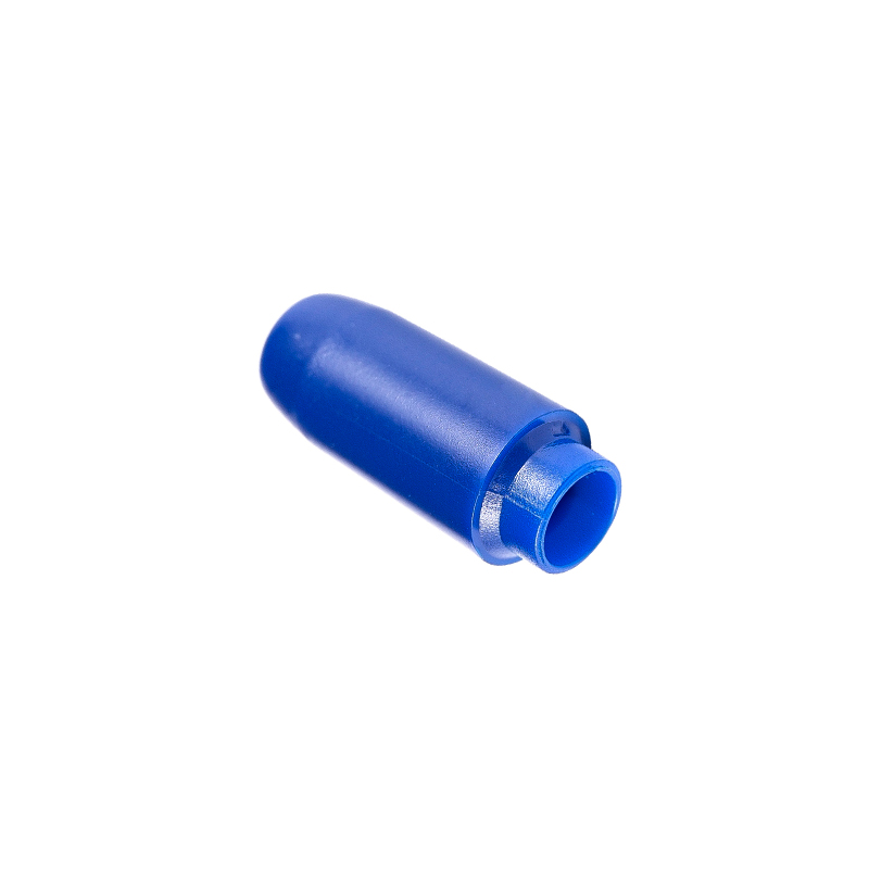
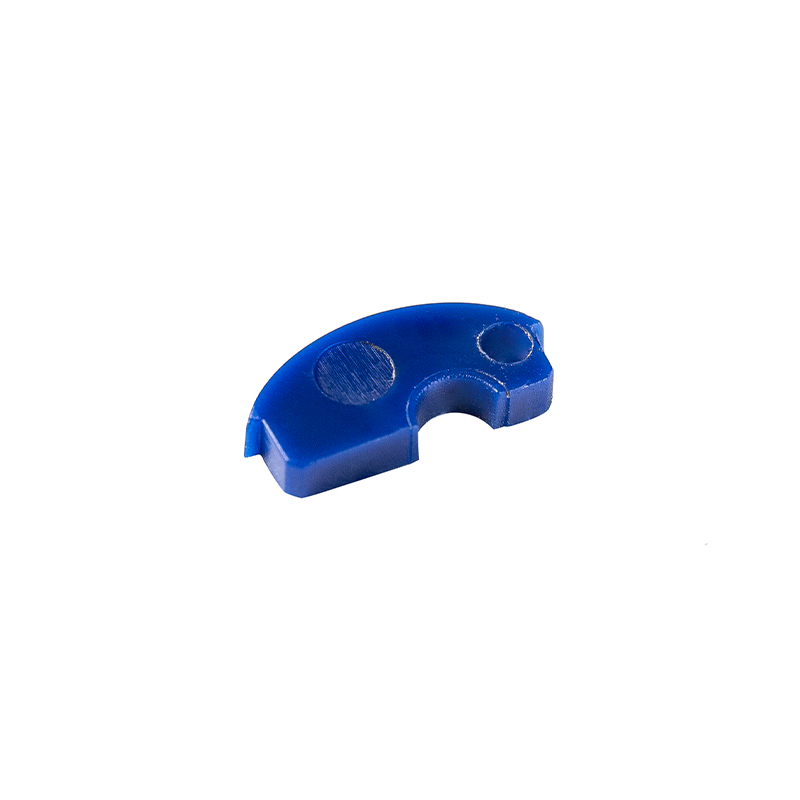
Precision injection molding automotive parts are components that must meet dimensional tolerances far tighter than standard plastic parts, typically in the range of ±0.05 mm to ±0.10 mm. These are the parts that snap-fit without gaps, seal without gaskets, and align across a vehicle's body with sub-millimeter accuracy. A headlight bezel, an airbag retainer, a fuel system connector — every one of these is a precision automotive plastic part that cannot deviate from its nominal geometry without creating a functional failure or a visible defect on the finished vehicle.
The definition of precision in automotive plastic component manufacturing is not arbitrary; it is driven by the assembly sequence. A dashboard carrier molded with a positional tolerance of ±0.3 mm might mate correctly to the body-in-white at one plant and the instrument panel at another. If the snap-fit attachments drift by even 0.2 mm, the result is a squeak, a rattle, or a warranty claim. Achieving this repeatability across millions of parts demands a rigorous integration of mold design, process control, and inspection — the three pillars of injection molding for automotive components at the precision end.
Automotive Injection Molding Design: Building Precision into the Part
Precision starts on the CAD screen. Automotive injection molding design for high-tolerance parts follows rules that general-purpose molding can afford to ignore. Wall thickness must be uniform to within ±0.05 mm to ensure even cooling; any variation creates differential shrinkage that pulls the part out of tolerance. The gate location is chosen not just for flow length but also to minimise the distortion at the weld lines where two melt fronts meet. For a connector housing with 48 pin holes, the gate must be positioned so that the melt front arrives at every pin core simultaneously, preventing core shift that would misalign the pins by more than 0.03 mm.
Mold tooling for automotive injection molded components incorporates features that maintain precision over the tool's life. Slides and lifters that form undercuts are built with preloaded guidance systems that wear less than 0.005 mm over 500,000 cycles. Cooling channels are positioned with conformal cooling, sometimes via 3D-printed inserts, to maintain a cavity surface temperature variation of less than ±3°C. These design decisions are validated through mold flow simulation that predicts not just fill pattern but also the post-molding warpage after 24 hours of cooling. The automotive plastic parts with complex geometries — a charge air duct with integrated sensor bosses, a coolant manifold with internal o-ring grooves — cannot be designed by trial and error; the simulation must be right the first time because the steel is already being cut.
Automotive Injection Molding Tolerances: Where the Numbers Come From
Automotive injection molding tolerances are not universally defined by a single standard; they depend on the material, the part size, and the functional requirement. The table below gives practical tolerance ranges for common automotive precision parts, based on the widely referenced DIN 16742 and the Society of the Plastics Industry (SPI) guidelines, adapted for typical automotive practice.
Typical linear tolerances for precision injection molded automotive parts by material and part size.
Material Group
Part Size < 50 mm
Part Size 50–150 mm
Typical Application
Unfilled (PP, ABS, PC/ABS)
±0.08–0.12 mm
±0.15–0.25 mm
Interior trim, bezels, covers
Glass-filled (PA6 GF30, PP GF20)
±0.05–0.10 mm
±0.12–0.20 mm
Engine covers, brackets, structural housings
High-precision (PBT, PPS, LCP)
±0.03–0.06 mm
±0.08–0.15 mm
Connectors, sensor housings, micro-switches
These tolerances are achievable only when the mold, machine, and material are controlled as a single system. A tolerance of ±0.03 mm on a small PBT connector implies that the mold cavity was machined to a tolerance of ±0.005 mm, that the injection unit delivers a shot weight repeatability of less than 0.1%, and that the material viscosity is consistent batch to batch. When a drawing specifies automotive injection molding tolerances at this level, the entire supply chain must be capable of statistical process control (SPC) and the mold must be qualified with a capability study demonstrating a Cpk of at least 1.33 for every critical dimension.
Automotive Plastic Parts with Complex Geometries: Overcoming Molding Challenges
Automotive plastic parts with complex geometries push injection molding to its limits. A single part may contain thin walls of 1.2 mm for weight reduction, thick bosses of 4 mm for threaded inserts, undercuts formed by four slides, and a surface finish that must be paint-ready without sanding. Molding such a part without warpage or sink marks requires a deep understanding of how the polymer shrinks as it transitions from melt to solid. The design must ensure that the cooling rate is as uniform as possible, because differential shrinkage — where a thin rib cools faster than the adjacent thick wall — is the primary cause of dimensional deviation in automotive plastic component manufacturing.
The mold maker's response to complexity is often multi-stage ejection and sequenced valve gates. A large instrument panel carrier, for example, may use six to eight sequentially controlled hot runner valve gates that open in a cascade, filling the cavity from the centre outward and preventing the weld lines that would appear if all gates opened simultaneously. The tool may also incorporate gas-assisted injection or water-assisted injection to hollow out thick sections, reducing weight and eliminating sink marks. These technologies are not added for novelty; they are the only way to produce automotive injection molded components that meet the dimensional and appearance standards of a modern vehicle interior. For parts like a full-length rocker panel molding with integrated clips, tabs, and a show surface, the successful mold is the one that manages the melt front and the cooling sequence to the millimetre.
Automotive Injection Molding Quality Control: From In-Mold Sensors to CMM
Automotive injection molding quality control for precision parts is not a final inspection step — it is embedded in every shot. Cavity pressure sensors mounted behind ejector pins monitor the pressure curve inside the mold in real time. A reference curve is established during process validation, and every subsequent shot is compared to it. If the peak pressure or the integral under the curve deviates by more than 2%, the part is automatically segregated. This detects not just short shots and flashes but also subtle variations in viscosity and packing that would produce a dimensionally out-of-tolerance part even though it looks perfect to the eye.
Beyond in-process monitoring, precision automotive plastic parts are sampled at defined intervals — typically every 2 to 4 hours — and measured on a coordinate measuring machine (CMM) or a vision system. The measurement data feeds a statistical process control chart that tracks key dimensions over the production run. If a critical dimension such as a snap-fit gap begins trending toward the upper control limit, the process is adjusted before a single out-of-spec part reaches the assembly plant. For safety-critical automotive injection molded components, this quality data is retained as part of the PPAP documentation and can be audited by the customer at any time. Full traceability from resin lot to finished part is now standard for Tier 1 suppliers, with a 2D data matrix code laser-marked on each part linking to the process parameters used when it was molded. This level of automotive injection molding quality control turns the molding cell from a black box into a transparent, validated manufacturing node.
Bringing It All Together: Precision as a Manufacturing System
The thread connecting precision injection molding automotive parts is not a single technology but a systems approach. The part designer specifies a draft angle, a wall thickness, and a tolerance that the molding process can deliver. The mold maker builds a tool that holds those tolerances over 500,000 cycles. The process engineer develops a molding window where cavity pressure, melt temperature, and cooling time stay within a defined envelope. The quality team monitors every critical dimension and intervenes before a trend becomes a defect. When any link in this chain weakens, the precision claim fails.
For the next generation of electric and autonomous vehicles, the precision demands will tighten further. High-voltage connectors that carry 800V must have zero-flash seals molded in liquid silicone rubber overmolded onto a rigid PPS frame. LiDAR housings must hold optical alignment features to within ±0.02 mm across a 300 mm span, placing them in the realm of optical injection molding. The manufacturers that can deliver these automotive plastic parts with complex geometries to validated tolerances, with full process traceability and zero-defect quality, will own the Tier 1 supply chain for the next decade. Precision is not an option; it is the baseline.




 English
 中文简体
中文简体